ECE4960-2022
Course on "Fast Robots", offered Spring 2022 in the ECE dept at Cornell University
This project is maintained by CEI-lab
Cornell University: ECE 4960/5960
Lab 5: Open Loop Control
Objective
The purpose of this lab is for you to change from manual to open loop control of the car. At the end of this lab, your car should be able to execute a pre-programmed series of moves, using the Artemis board and two dual motor drivers.
Parts Required
- 1 x R/C stunt car
- 1 x SparkFun RedBoard Artemis Nano
- 1 x USB cable
- 1-2 x Li-Ion 3.7V 400mAh (or more) battery
- 2 x Dual motor driver
Prelab
Check out the documentation and the datasheet for the dual motor driver.
Note that to deliver enough current for our robot to be fast, we will parallel couple the two inputs and outputs on each dual motor driver, essentially using two channels two drive each motor. This means that we can deliver twice the average current without overheating the chip. While it is a bad idea to parallel couple motor drivers from separate ICs because their timing might differ slightly, you can often do it when both motor drivers are onboard the same chip with the same clock circuitry.
Discuss/show how you intend to hook up the motor drivers.
- What pins will you use for control on the Artemis? (It is worth considering both pin functionality and physical placement on the board/car).
- We recommend powering the Artemis and the motor drivers/motors from separate batteries. Why is that?
- Consider routing paths given EMI, wire lengths, and color coding. Long wires may not fit in the chassis, and lead to unnecessary noise. Wires that are too short, will make repair harder. Using solid-core wire can cause problems when the car undergoes high accelerations.
Lab Procedure
- Connect the necessary power and signal inputs to run one motor driver (with parallel coupled outputs) from the Artemis. For now, keep the motor driver (VIN) powered from an external power supply with a controllable current limit; this will make debugging easier.
- What are reasonable settings for the power supply?
- Use analogWrite commands to generate PWM signals and show (using an oscilloscope) that you can regulate the power on the output for the motors.
- Take your car apart!
- Remove the battery from your car. Unscrew and remove the top (blue) shell from your car. You may have to cut the wires for the chassis LEDs (we will not be using them in this class). Don’t loose the screws!!
- Locate and unmount the control PCB and cut wires to the motors and the battery connector as close to the board as possible.
- Connect the 650mAh battery that came with the car to the Artemis board. You will need to solder on the JST connector. Be careful not to short the battery leads when you do this. Cut, solder, and add heat shrink to one wire at a time.
- Keep the motor driver powered on an external power supply for now, but remember to connect all grounds in your circuit.
- Place your car on its side, such that the spinning wheels are elevated, and show that you can run the motor in both directions.
- Hook up the motor driver to the original battery leads from the car, and attach a 850mAh battery instead of a power supply (double check color codes before you plug it in), and make sure your code works when the circuit is fully battery powered.
- Repeat the process for the second motor and motor driver. One 850mAh battery should be enough to power both motors.
- Install everything inside your car chassis, and try running the car on the ground.
- Remember, the car may flip, so try to avoid having components that stick out beyond the wheels.
- Also, the car is very fast, so test in in the hallway and add a timer in code so that it stops automatically after a short amount of time. That way you don’t have to try to catch it when it gets away from you!
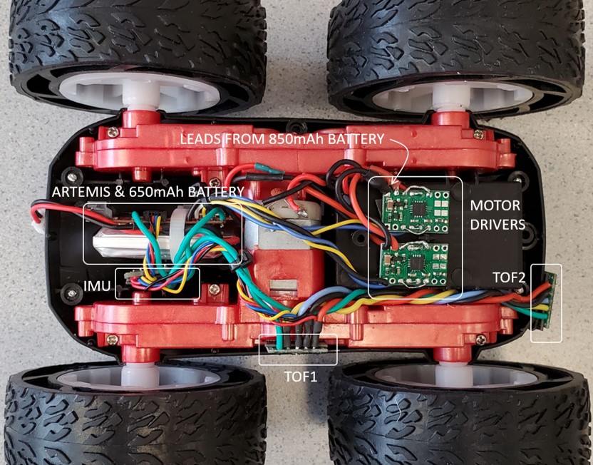
- Here is an example of a car with everything hooked up, but remember that the implementation details are entirely up to you:
- Explore the lower limit for which each motor still turns while on the ground; note it may require slightly more power to start from rest compared to when it is running.
-
If your motors do not spin at the same rate, you will need to implement a calibration factor. To demonstrate that your robot can move in a fairly straight line, record a video of your robot following a straight line (e.g. a piece of tape) for at least 2m/6ft. The robot should start centered on the tape, and still partially overlap with the tape at the end.
- Demonstrate open loop, untethered control of your robot - add in some turns.
- (Optional) For fun, you can make the robot run only when it hears loud frequencies like this version from past semesters:
 .
.
Additional tasks for ECE5960 students
-
Consider what frequency analogWrite generates. Is this adequately fast for these motors? Can you think of any benefits to manually configuring the timers to generate a faster PWM signal?
-
Write a program that ramps up and down in speed slowly. Reporting the values to your computer using Bluetooth either during operation or when your ramp up/down procedure is over. Use this setup to document accurately what range of speeds you can achieve. (If your sensors are still attached, it may be easiest to use them to help you determine speed).
Write-up
To demonstrate that you’ve successfully completed the lab, please upload a brief lab report (<800 words), with code snippets (not included in the word count), photos, and videos documenting that everything work and what you did to make it happen.