ece3400-2017
ECE 3400 Intelligent Physical Systems course web page and assignments
This project is maintained by CEI-lab
ECE3400 Fall 2017
AutoCAD Wheel Demo
By Christopher Fedors, July 30th 2017
This tutorial has been turned into a video available here.
Alternatively, if you prefer the step-by-step version, see below:
Getting Started
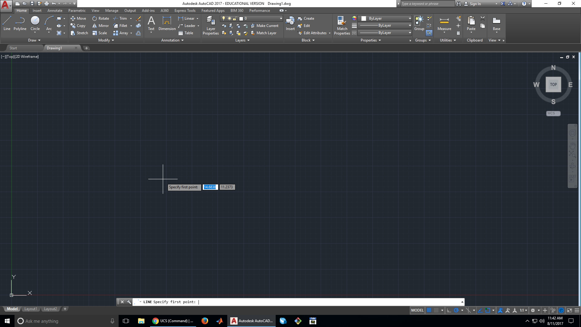
1. Open up a new drawing file in AutoCAD


2. Start by drawing a line
We want this wheel to have a notch in it, so we are going to start by making the profile of the wheel. This first line is going to determine the radius of our wheel, so we set it to 1.25 in.

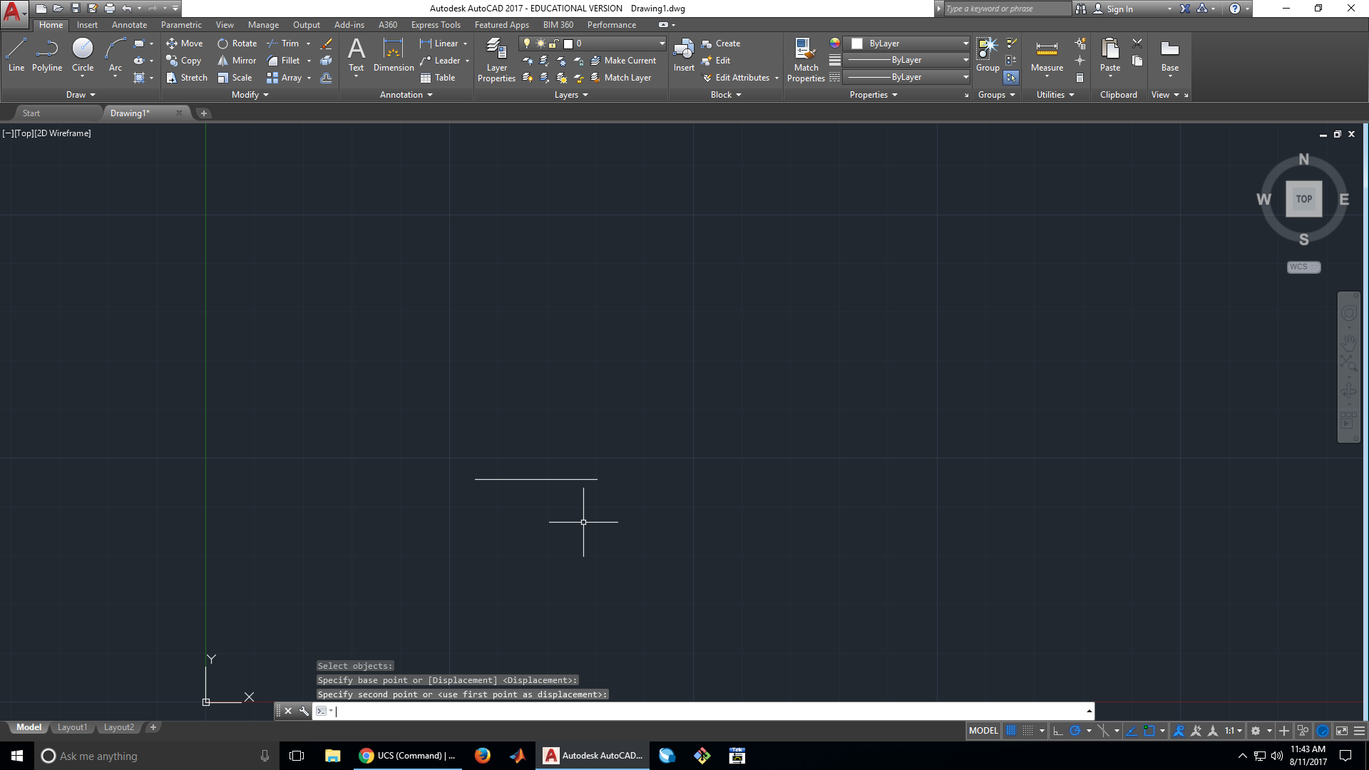
3. Move the line closer to the origin
Our line is kind of far from the origin, so its a good idea to move it closer. The origin will help keep us oriented as we continue our design.


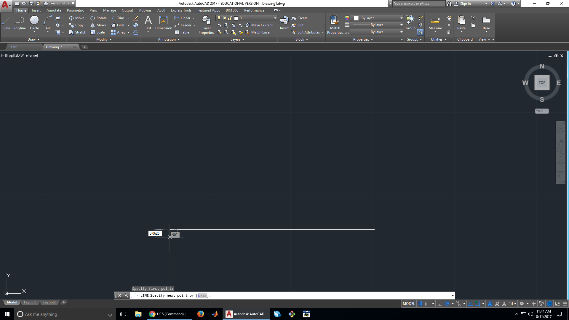
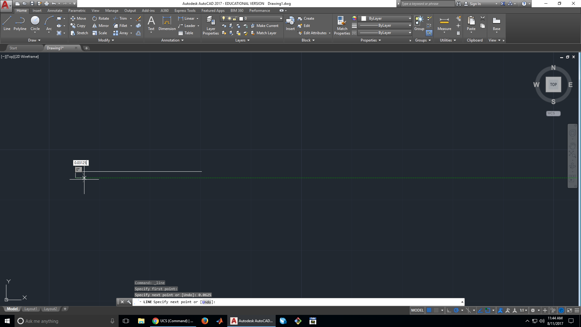
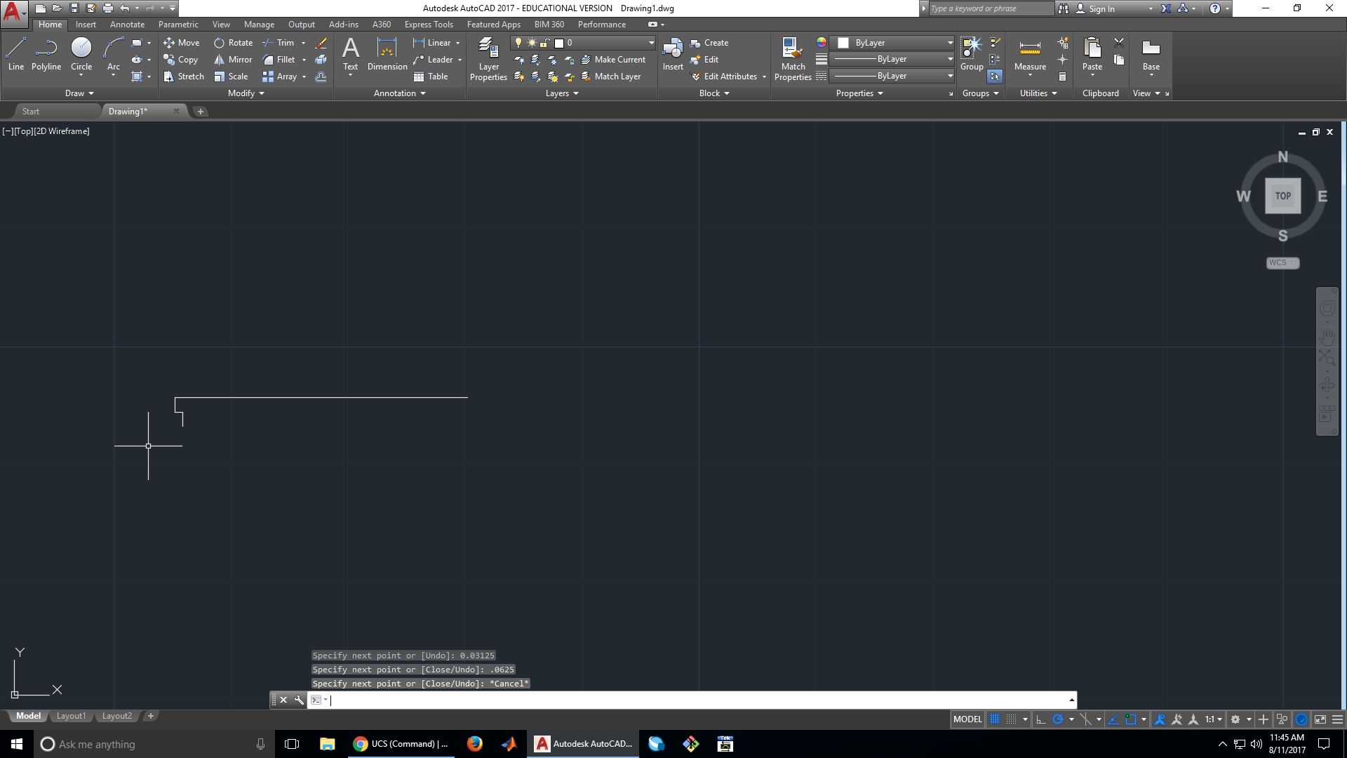
4. Start work on the wheel’s profile
We want our notch to be 0.125 in. wide, with 0.0625 in. walls on the side. Since the wheel is symmetrical, we can just draw half of the wheel and mirror it, saving us work.
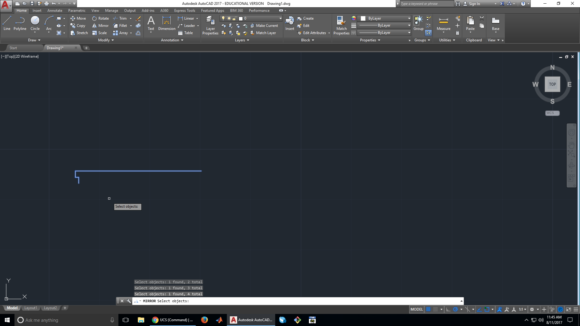
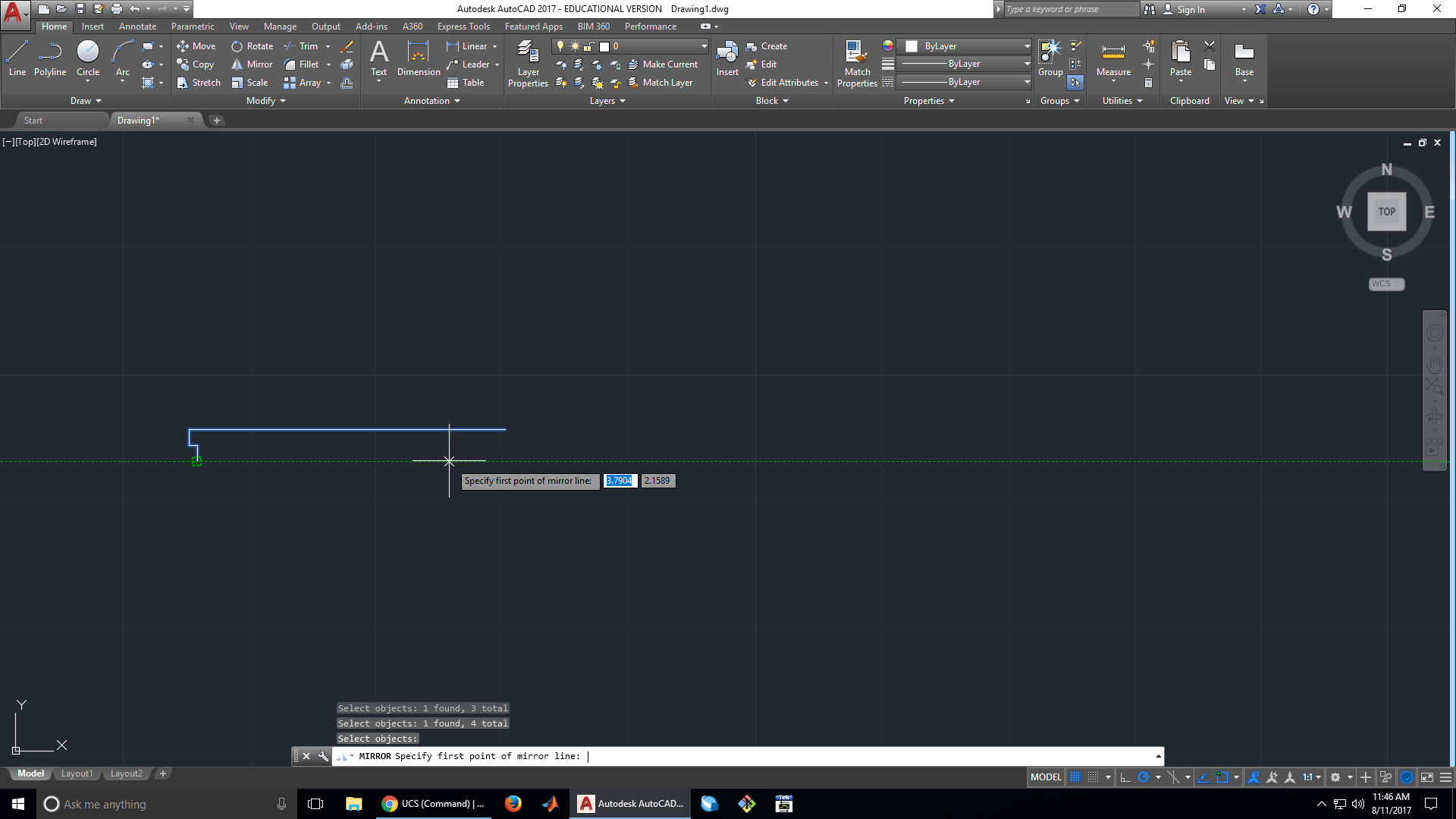
5. Mirror the wheel’s profile


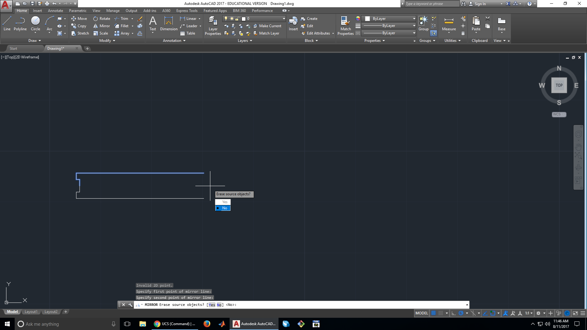
6. Finish the profile
After mirroring the profile, we need to close off the end.

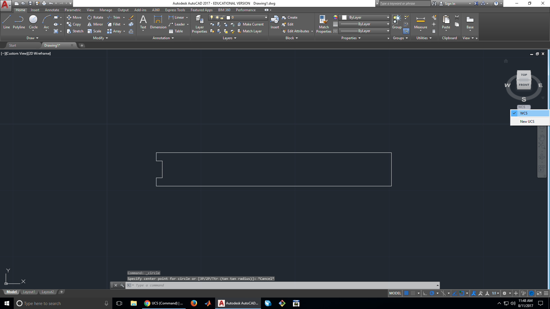
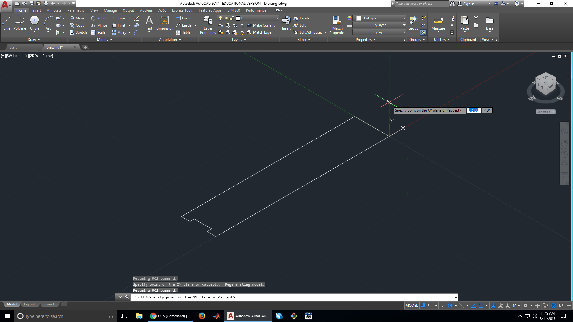
7. Change the User Coordinate System (UCS)
The next thing we want to make after the profile is done are spokes for the wheels, as well as the holes for the screws. To do this, we need to create a new coordinate system at 90° to the one we’ve been using so far. We pick a convenient origin, then place our X axis on the old X axis and the Y axis on our old Z axis.


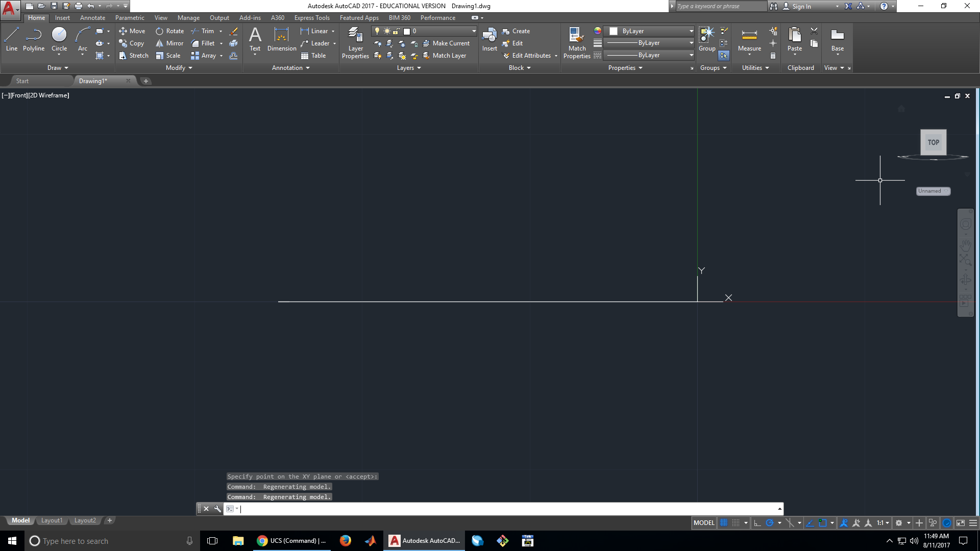
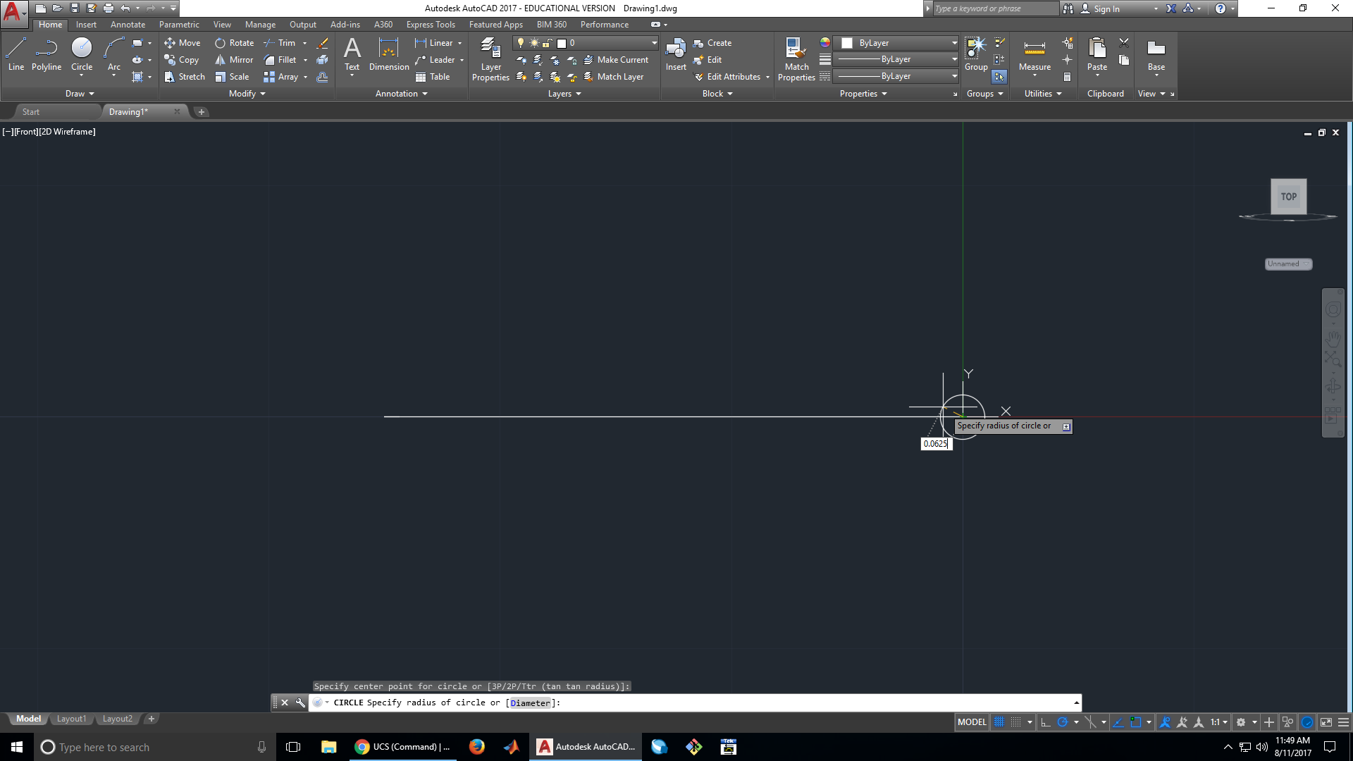
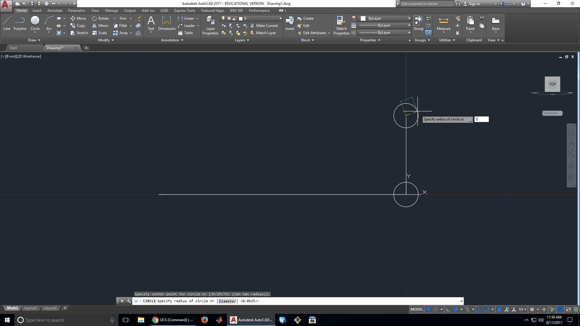
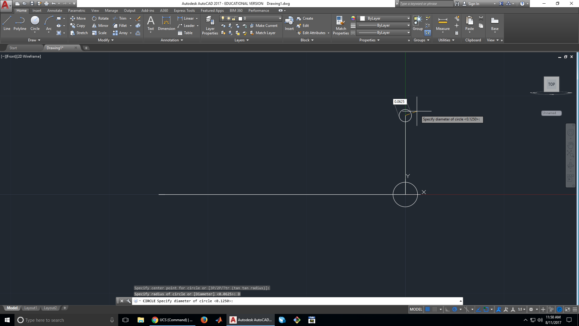
8. Make the center screw hole
This is hole that will be used to connect the servo to the wheel. The way this works is that the wheel will be a attached to a servo adapter, which has four holes to screw into the wheel. There is a fifth screw that screws the servo adapter into the servo. This screw must be able to fit through a hole in the center of the wheel in order to screw the servo adapter into the servo. To accommodate this, we make the center hole the largest. In this tutorial the center hole has a diameter of 0.125 in., which is much too small for the servo adapters we use. The hole should actually be 0.25 in. in diameter.
9. Make a mounting hole
These holes attach the wheel to the servo adapter. There are four of them, located 0.4 in. from the center of the wheel. They are made 0.0625 in. in this tutorial, and should be made 0.125 in. in diameter to fit the screws used in this class. In this tutorial, we are going to use a polar array to make three more copies of this hole later, so we only need to make one mounting hole for now.
We start by making a line 0.4 in. in order to establish the right distance between the center of the wheel and the mounting hole

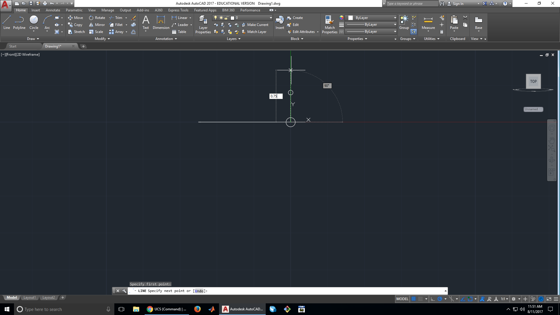
10. Make a spoke
While not structurally necessary, spokes in the wheel reduce the amount of material the wheel needs if it is 3D printed, as well as its moment of inertia. We will be adding 6 spokes with 30° widths and 0.25 in. heights. We will start by making one spoke, then use a polar array to create the other 5 spokes.
As with the mounting holes, we start by specifying the distance the spoke will be from the center of the wheel. This time, the spoke will be 0.75 in. from the wheel’s center.
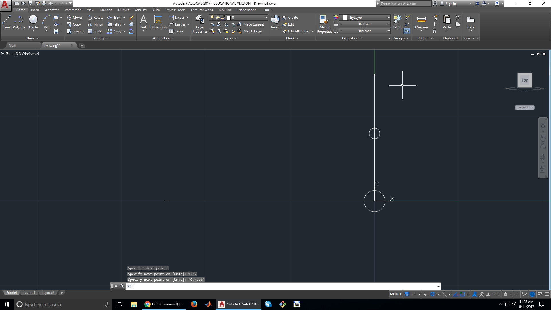

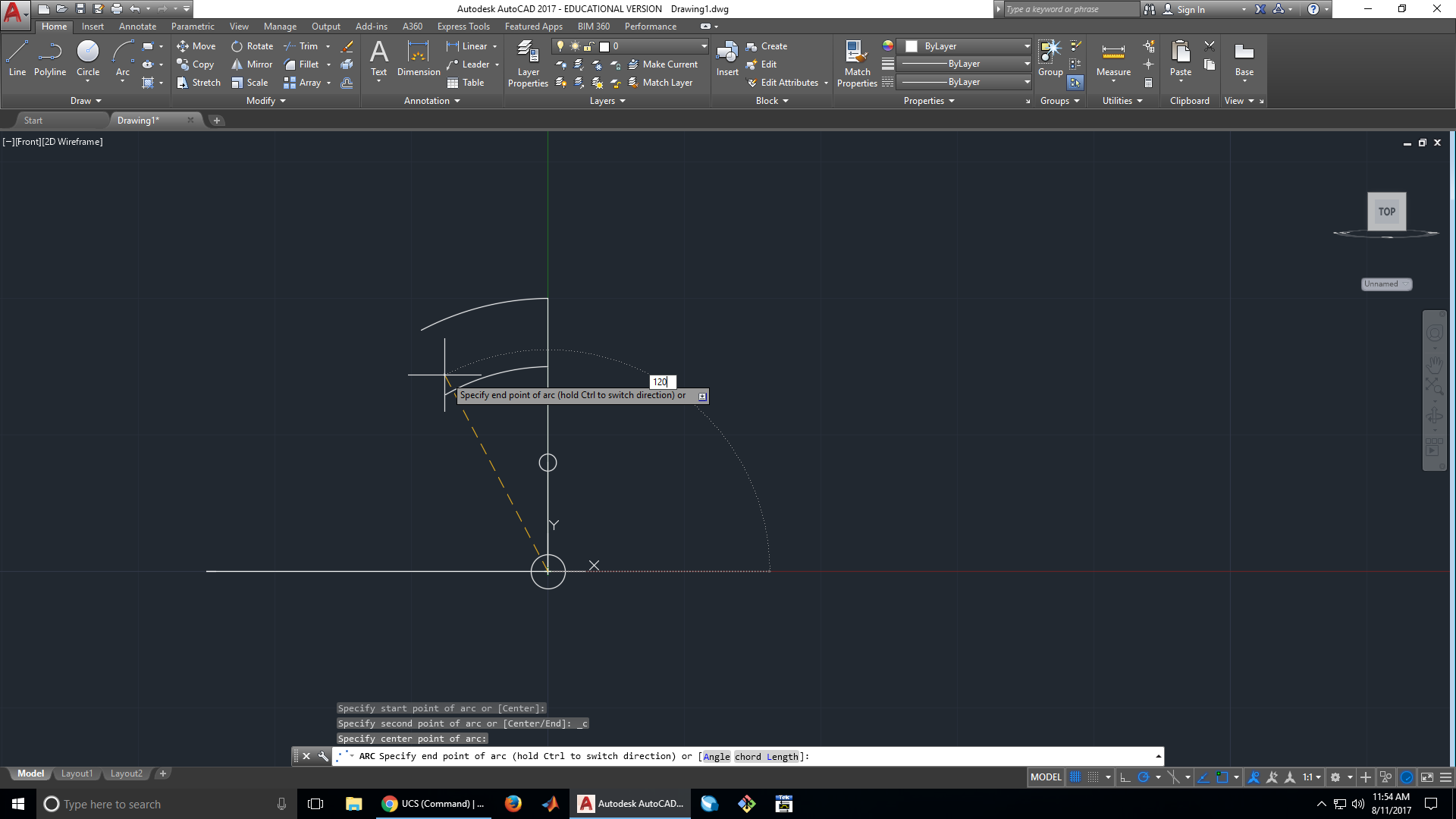
To make 30° segments, we will use the arc tool. The most useful arc tool for this application is the start, end, center tool. We use the end our line segment as the start point, the wheel’s center as the centerpoint, then set the angle to 30°.

Here we set the height of the spoke to 0.25 in. using another line segment.


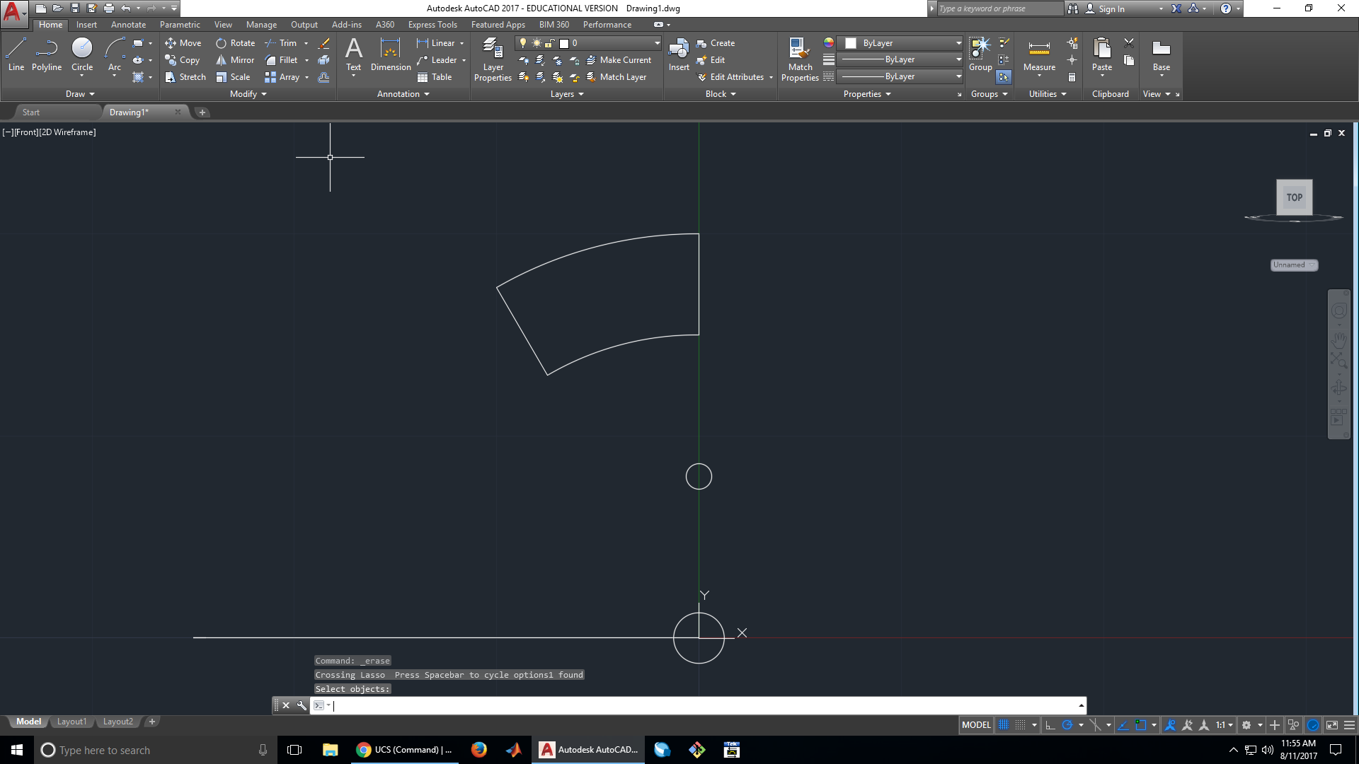
11. Delete the temporary lines
After we have made our spoke and mounting hole, we have not need for the lines we used to specify their distances from the center of the wheel. At this point we can delete this lines to remove some clutter.

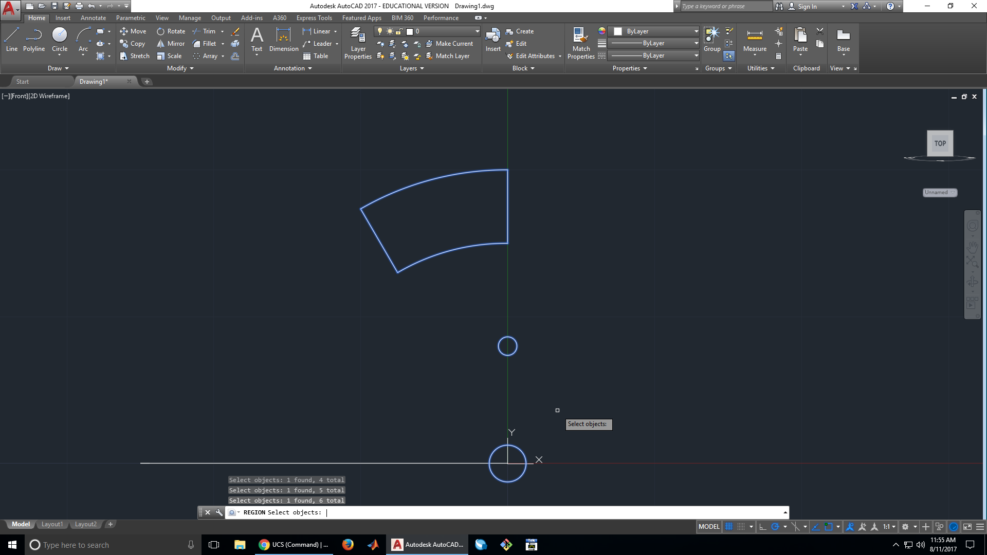
12. Turn the holes into regions
In order to manipulate the holes we made as 2D surfaces, we must convert them into regions. Since regions are not visible in 2D wireframe, we switch to conceptual view to make sure we created the proper regions.

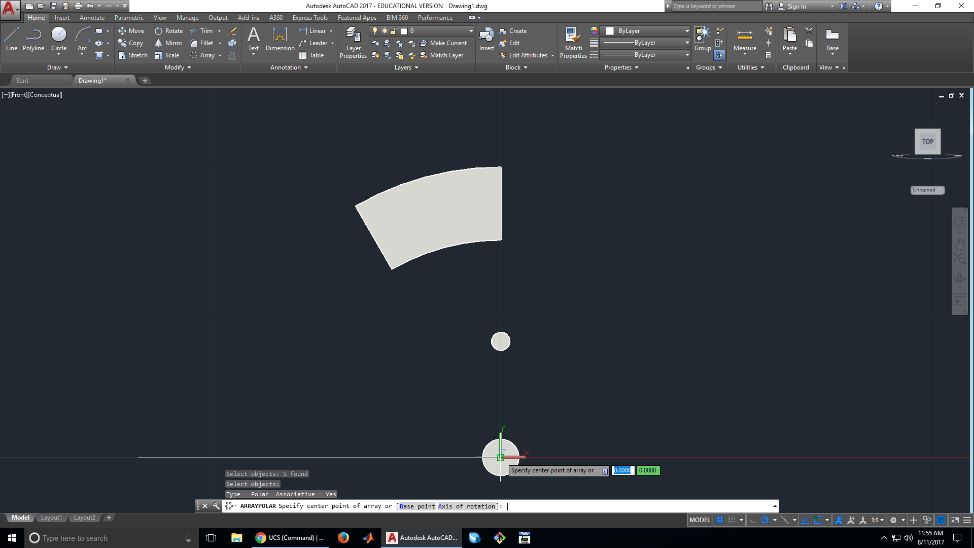
13. Use a polar array to make the spokes
Polar arrays make it easy to create multiple objects in a circular pattern. To turn out spoke region into a polar array, we select it using the polar array tool,
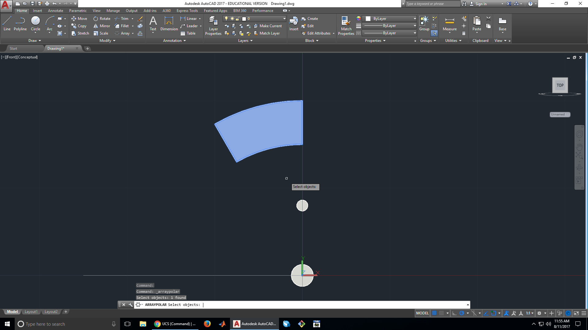
then specify the origin as the center of our wheel.
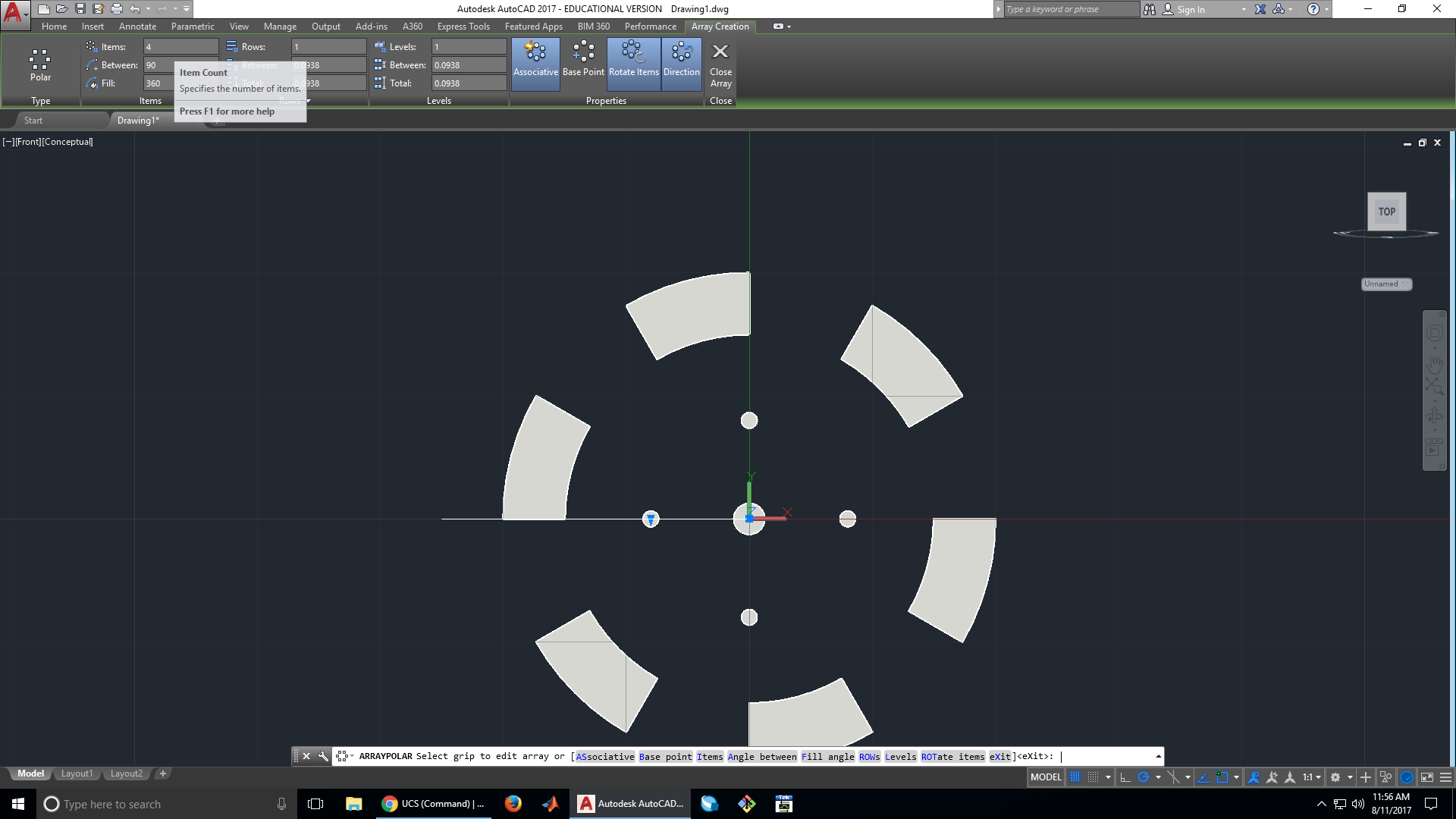
We then set the number of elements in the array to 6 to get the number of spokes we desire.

14. Use a polar array to make the mounting holes
To do this, we use the same steps used to make the spokes, but change the number of elements in the array to 4.

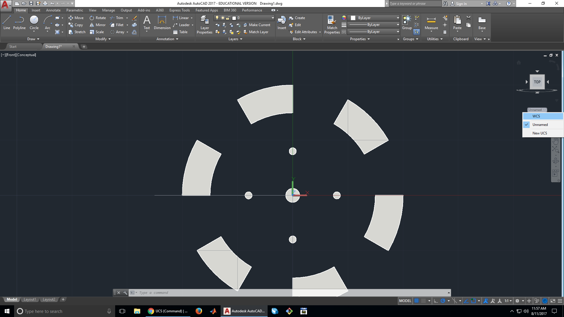
15. Revert back to the WCS coordinate system
At this point, we are done working on the face of the wheel and can switch back to the wheel profile.

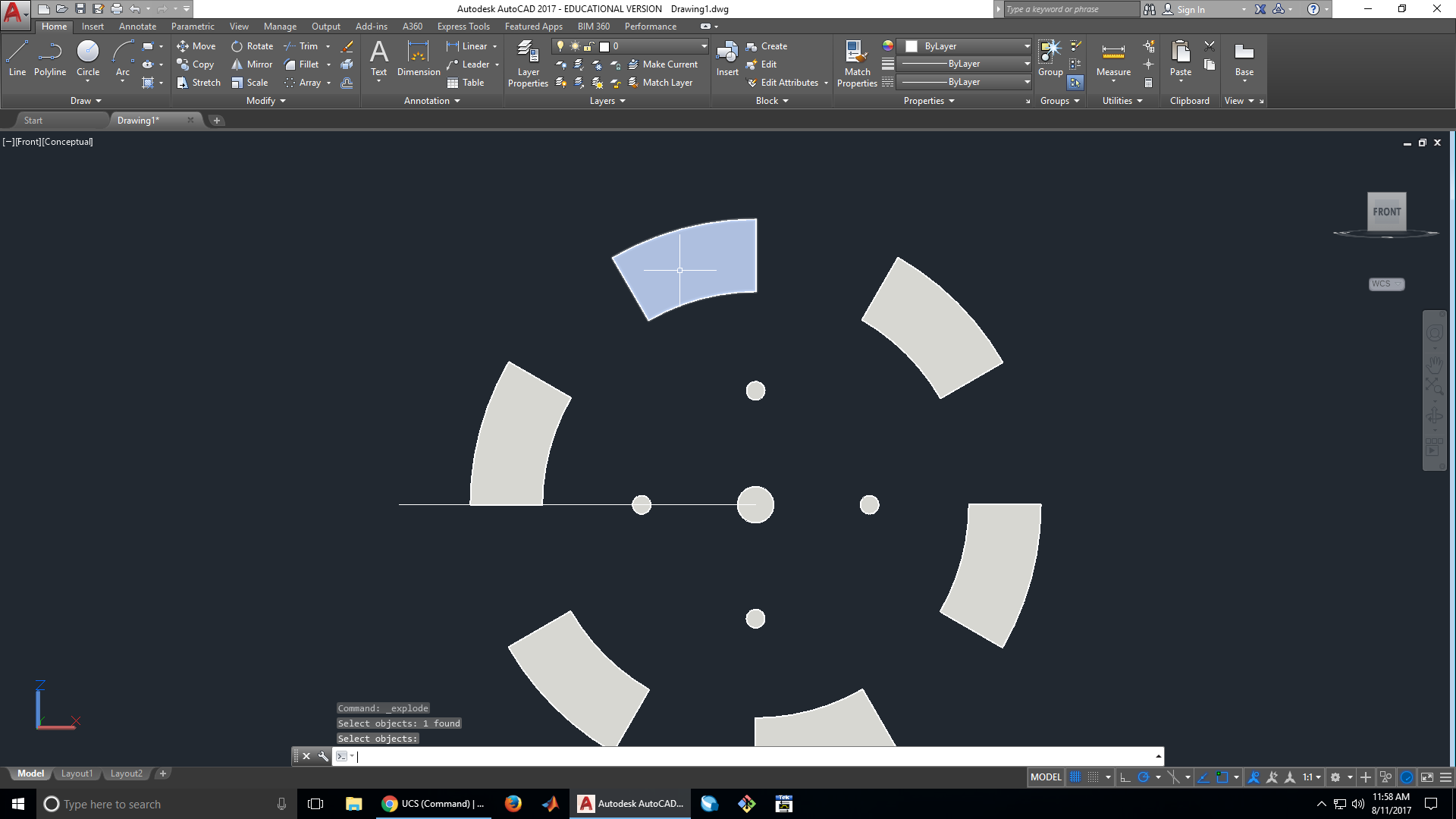
16. Explode the polar arrays
Since we cannot extrude arrays, we have to use the explode tool on the spokes and mounting holes to free them from their polar arrays.

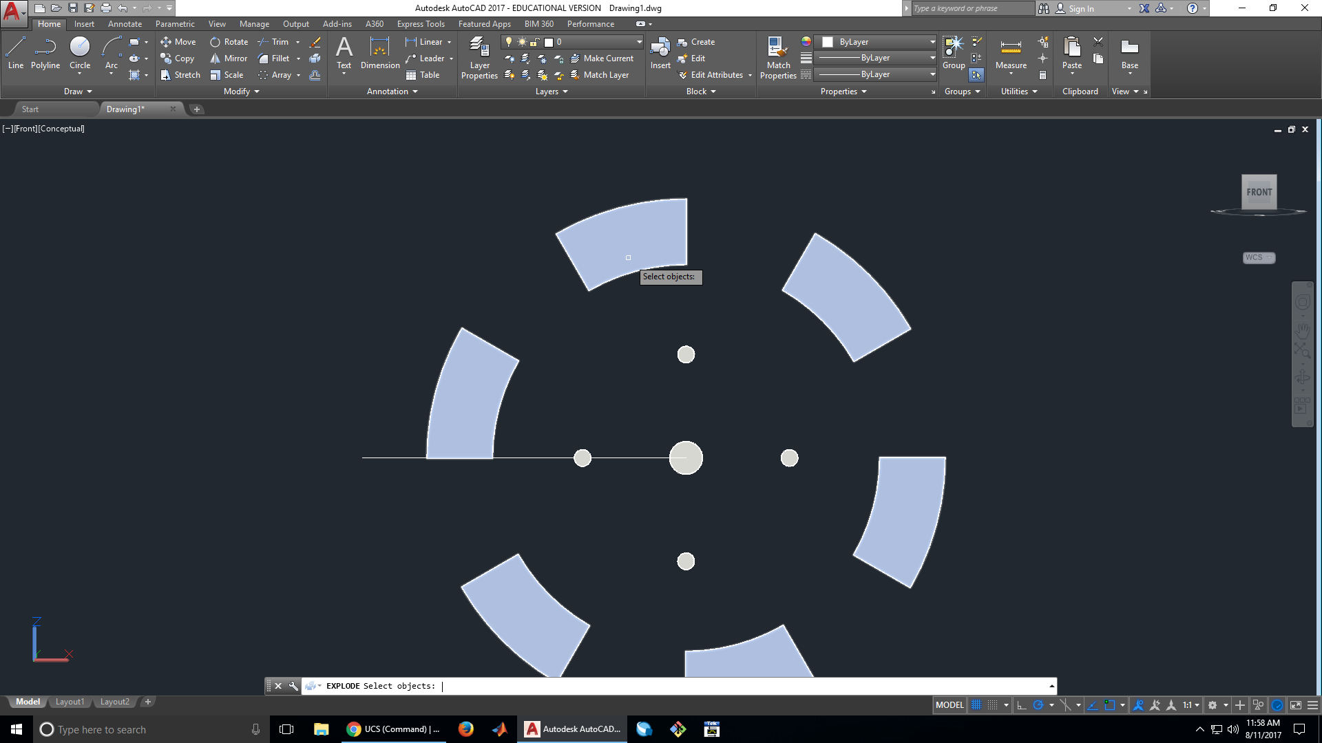

Check that the explode operation worked properly by trying to select a spoke or mounting hole. If it worked, you will be able to select each spoke and hole individually.

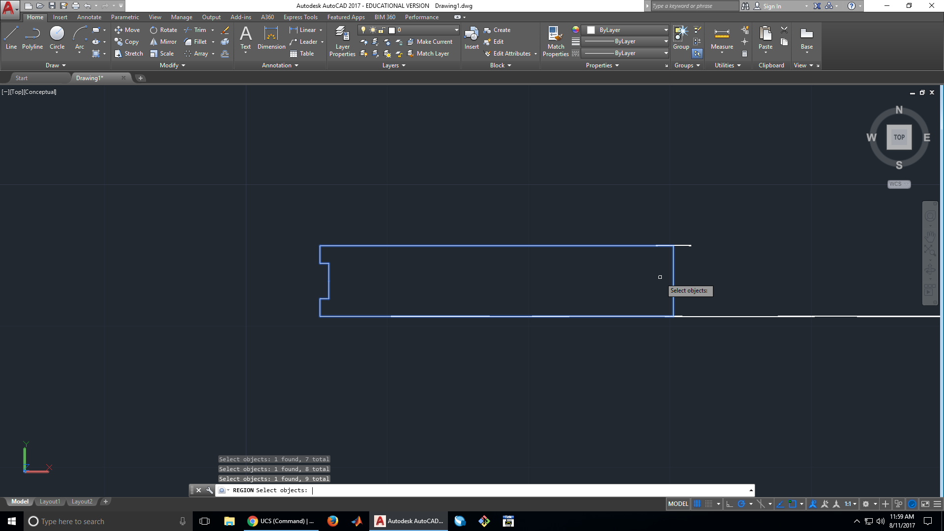
17. Turn the wheel profile into a region
Since we want the wheel to be solid and not hollow, we turn the profile we made earlier into a region. Revolving or extruding an outline creates a hollow object, while doing the same with a region creates solid objects.
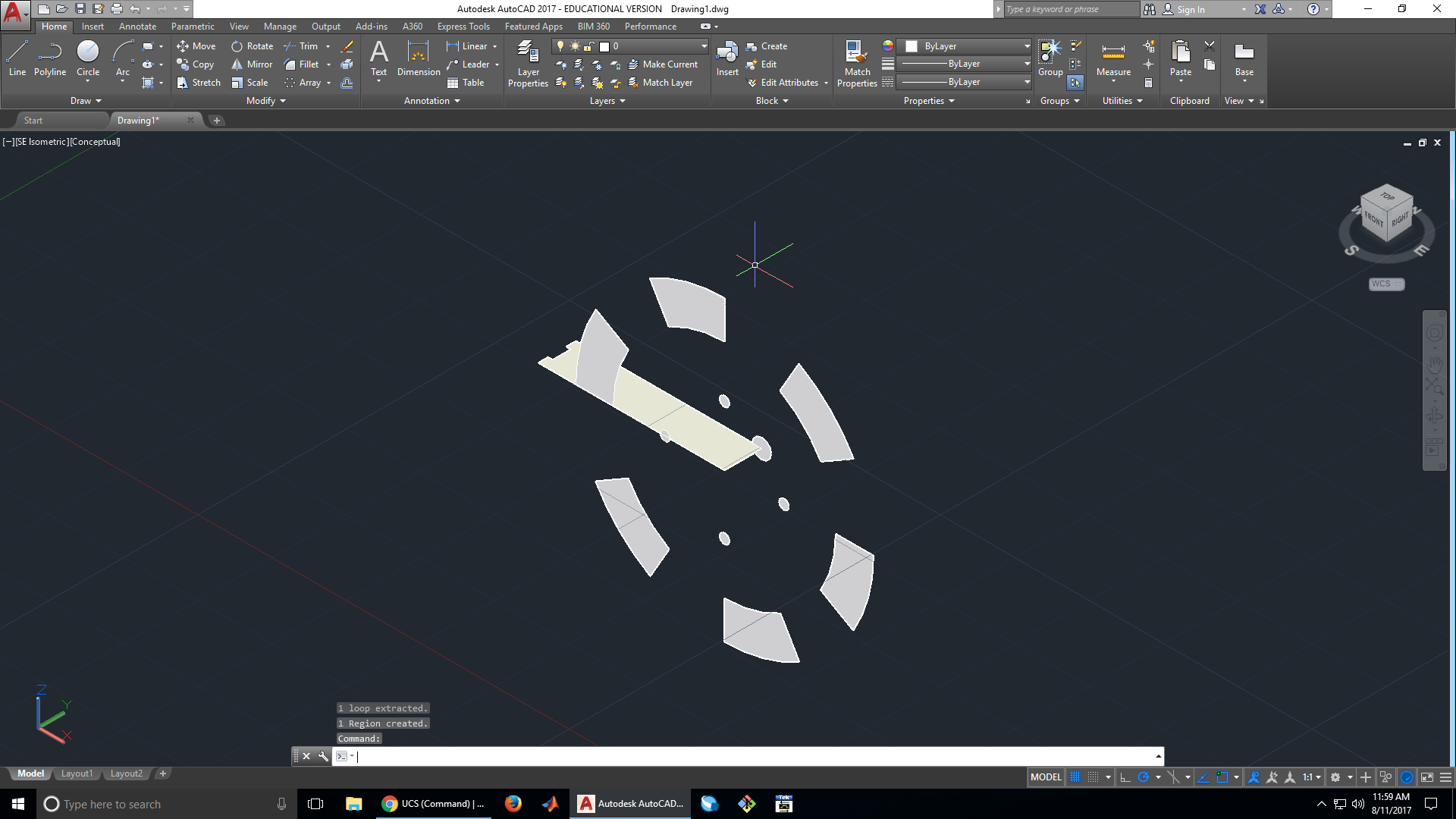
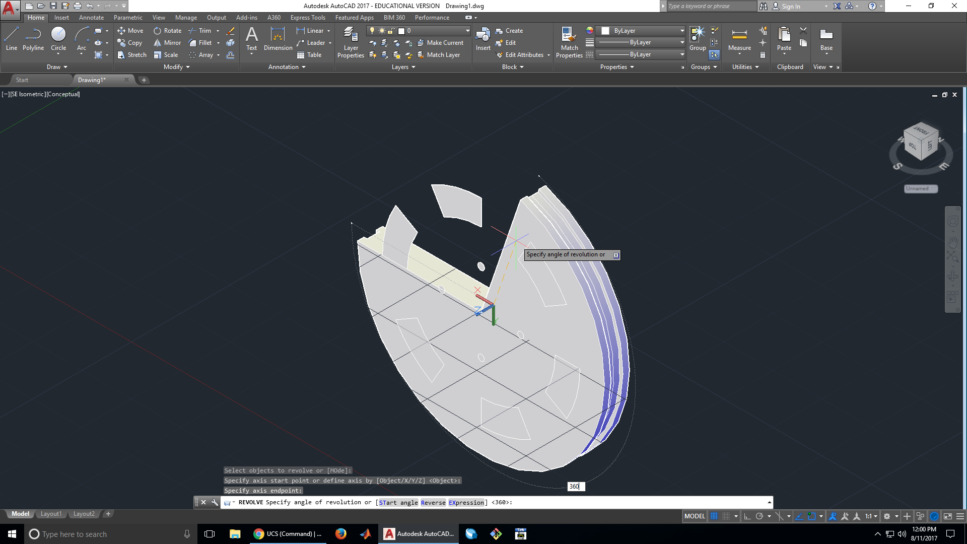
18. Revolve the wheel profile 360°
This will create the shape of our wheel. To use the revolve tool, we first must select the object we want to revolve, then the specify the axis we want to revolve it around.
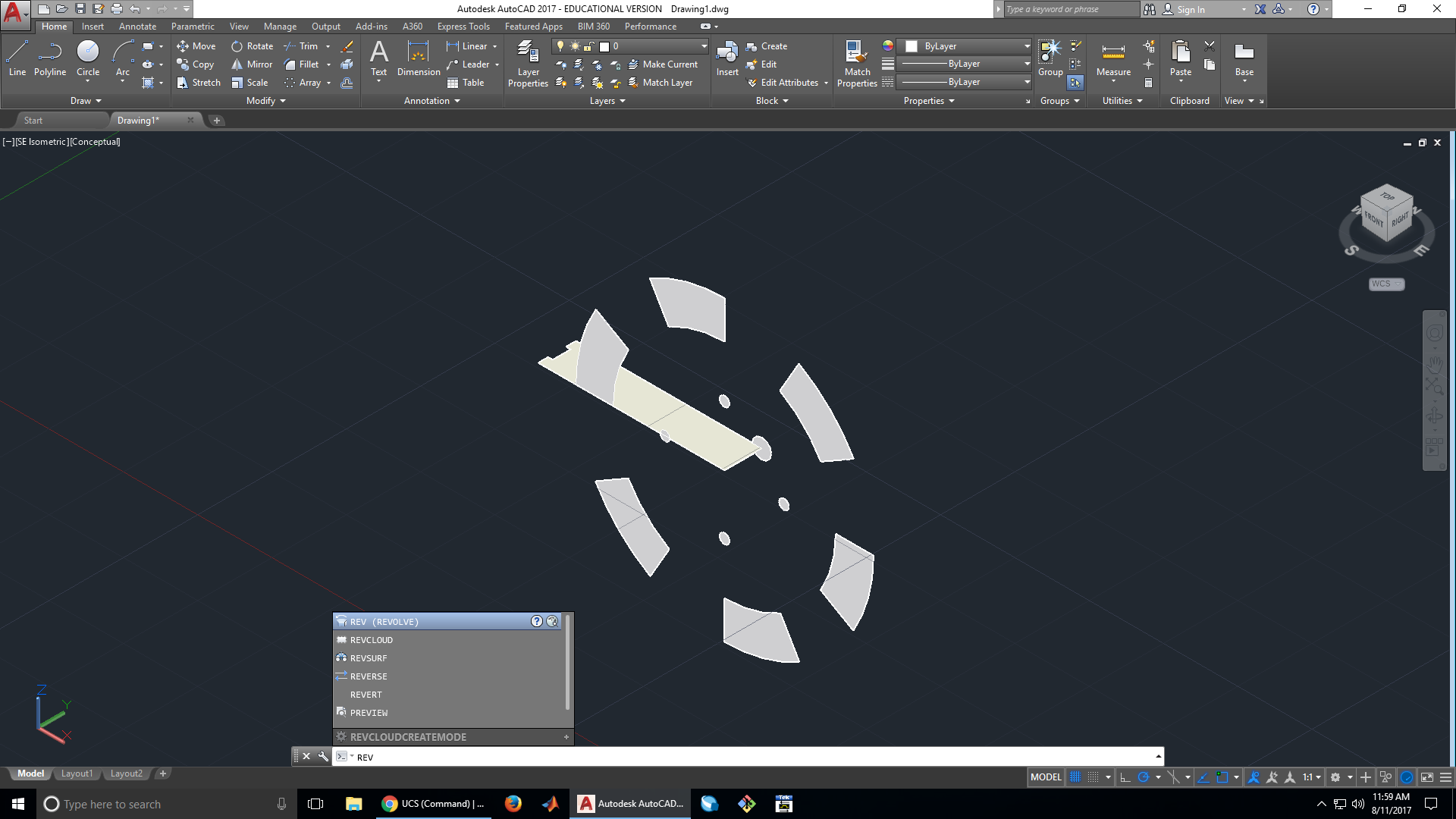


We specify that we want to revolve our profile 360°.
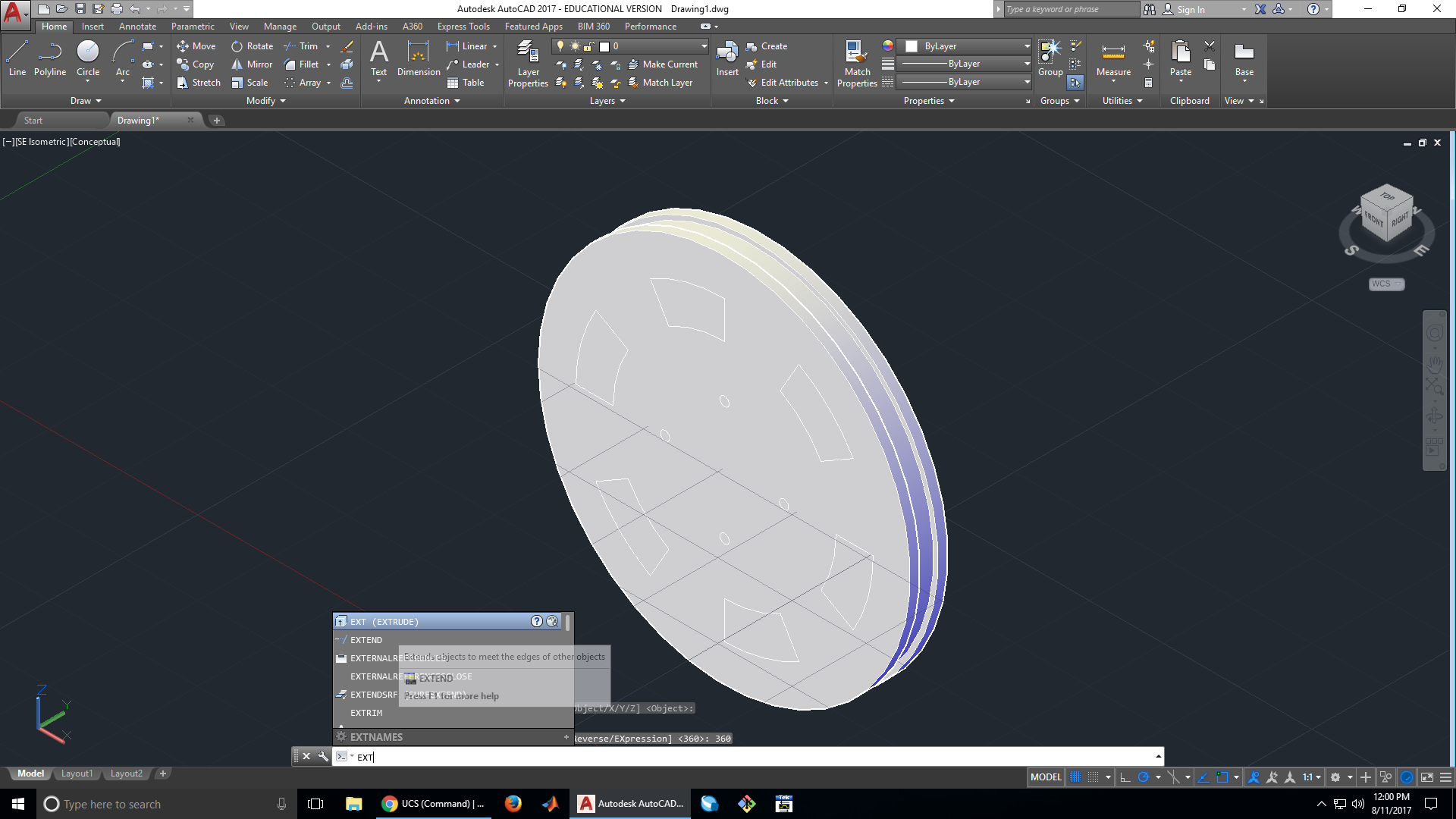
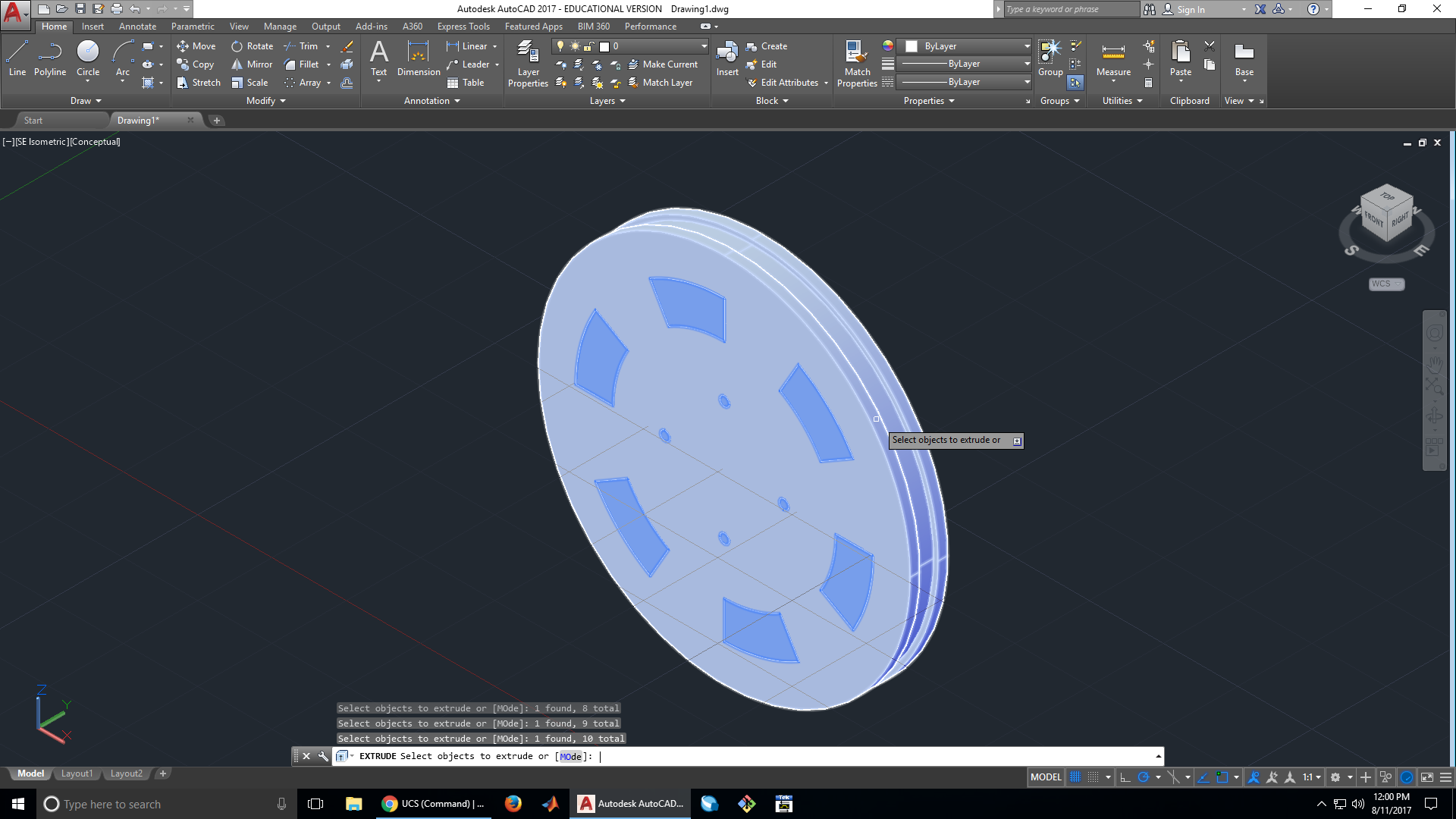
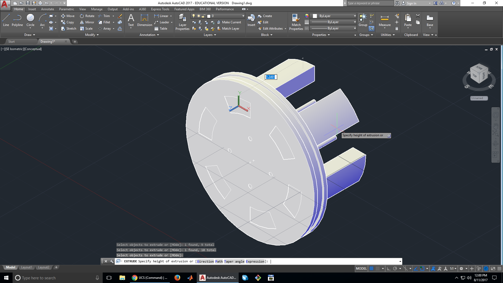
19. Extrude the spokes and holes
In order to create holes in the wheel, we are first going to extrude the hole surfaces we have made, then use the subtract tool to subtract the hole surfaces from the wheel. Using this method, we don’t have a specified height we need to extrude, we just need to extrude the hole surfaces further than the thickness of the wheel.

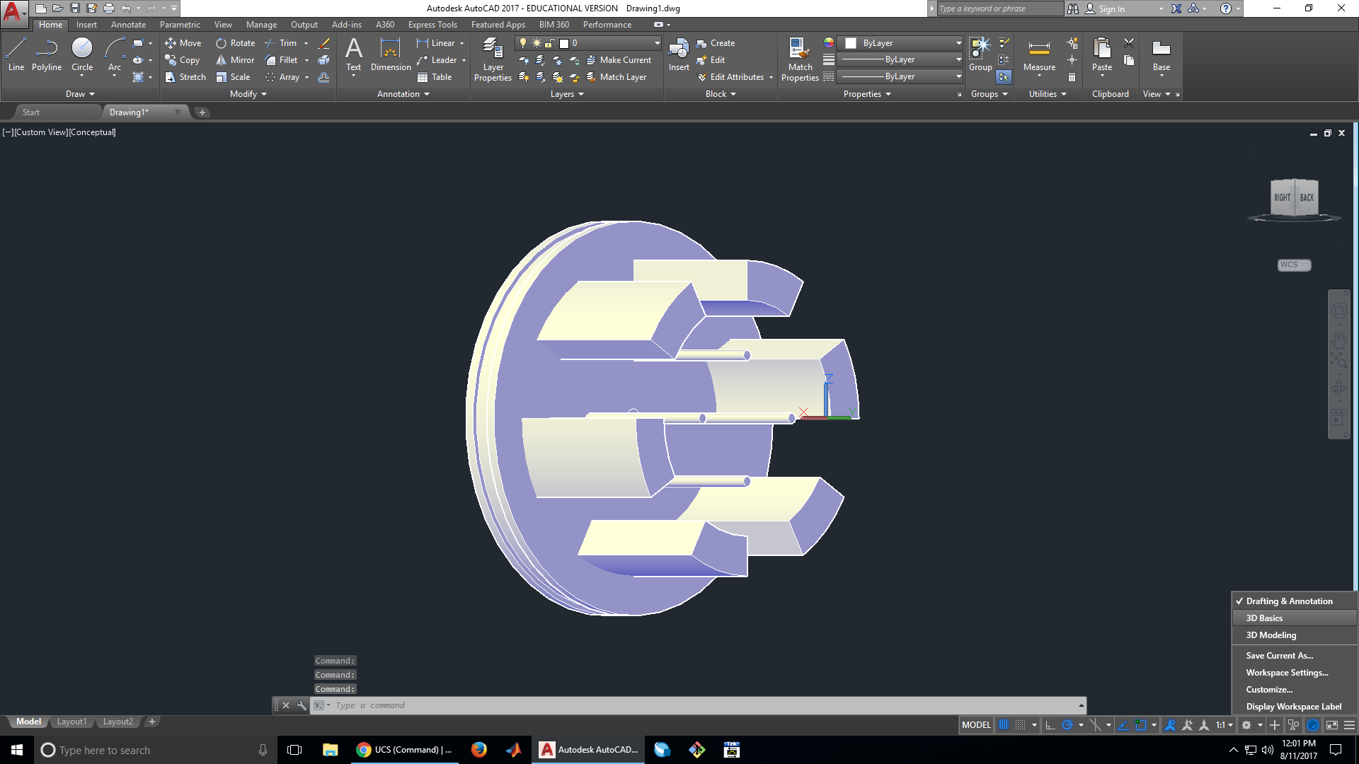
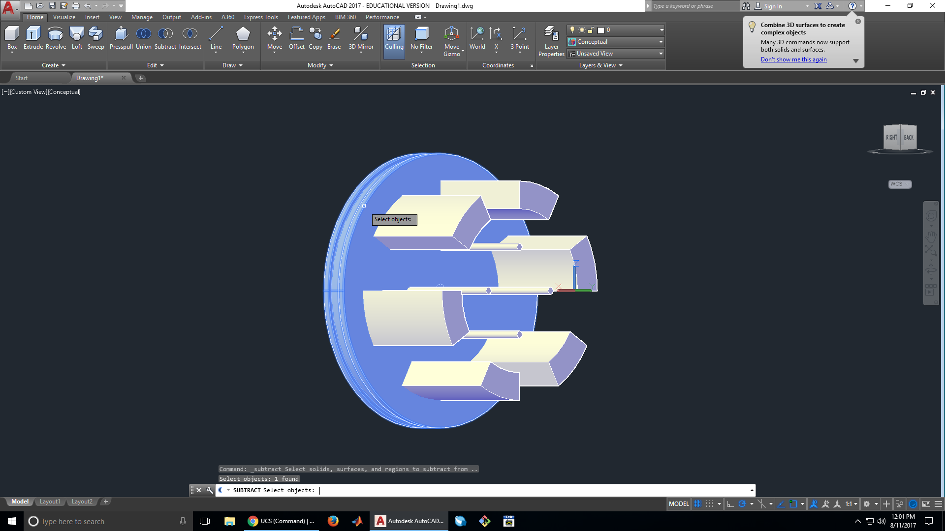
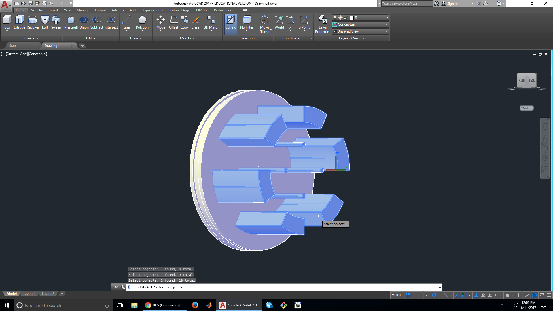
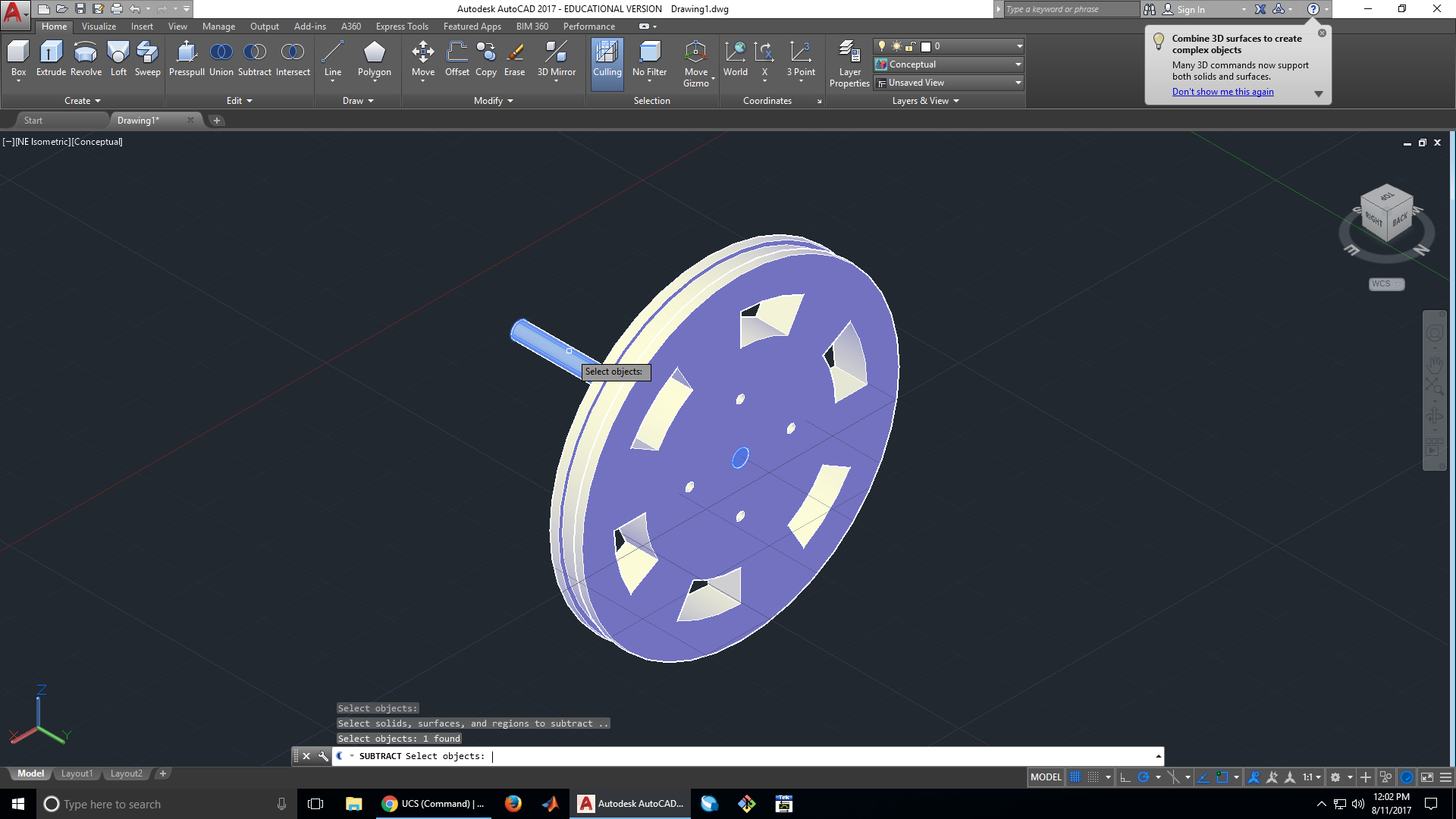
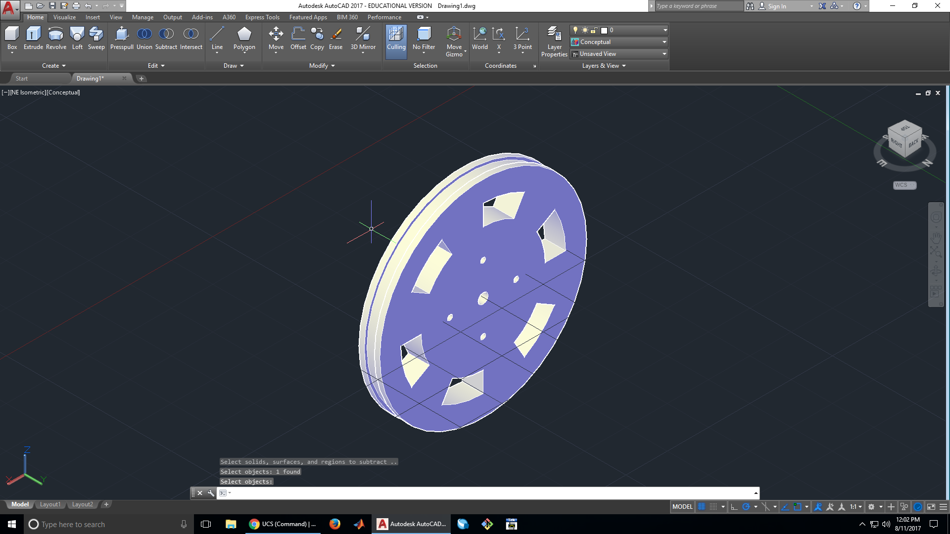
20. Subtract the spokes and holes from the wheel
Using the subtract tool, we can subtract out the material from the spokes and mounting holes from the rest of the wheel. Here we also change our workspace to 3D modeling in order to have easier access to the tools we need to use.

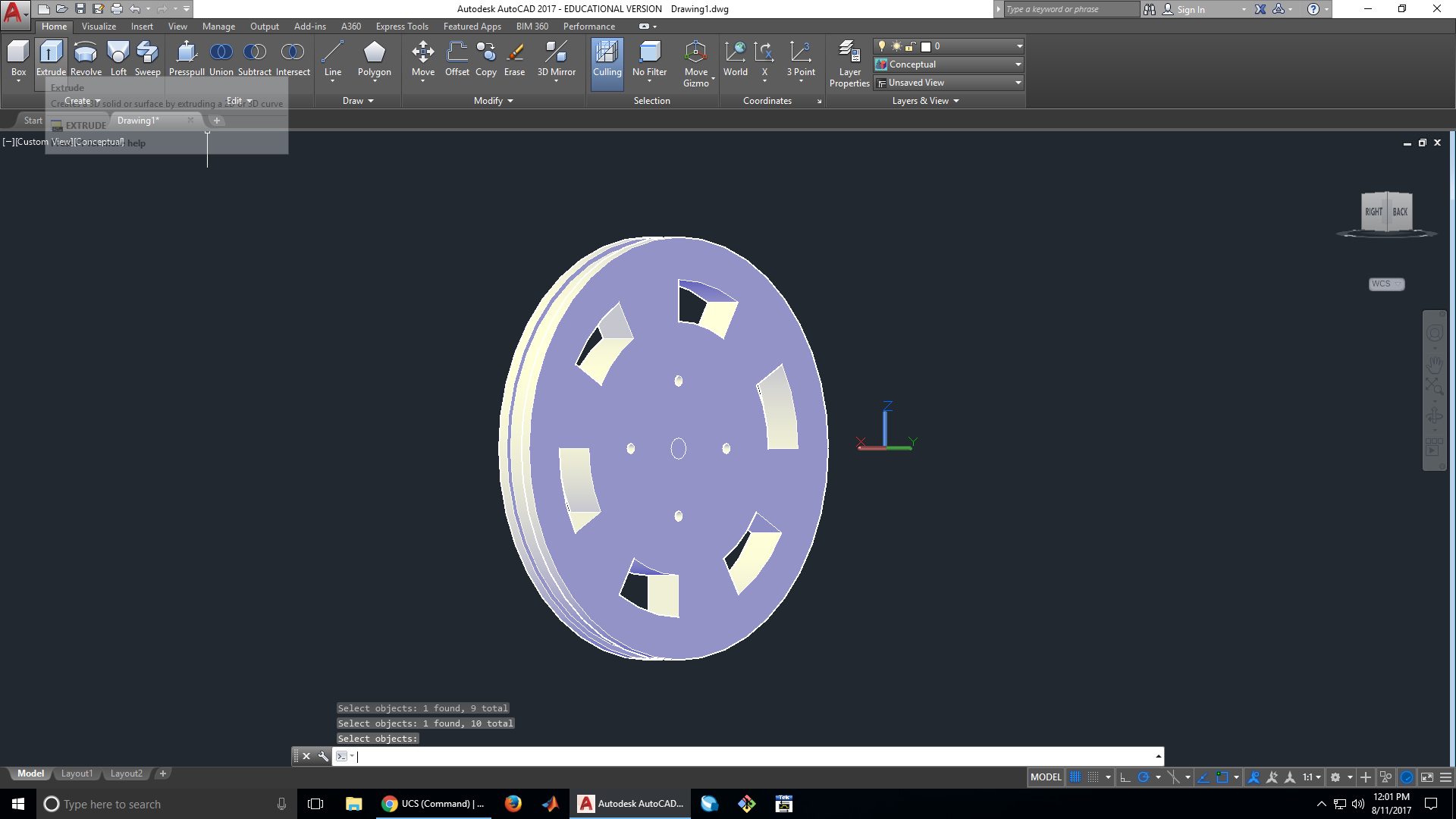
21. Extrude and subtract the center hole from the wheel
Since the area for the center hole was placed on the other side of the wheel, we have to extrude and subtract it separately.


22. Rotate the wheel
Since we want to 3D the wheel later, we need to rotate it so that it lies flat on the XY plane. This is the easiest position for it to be printed in.


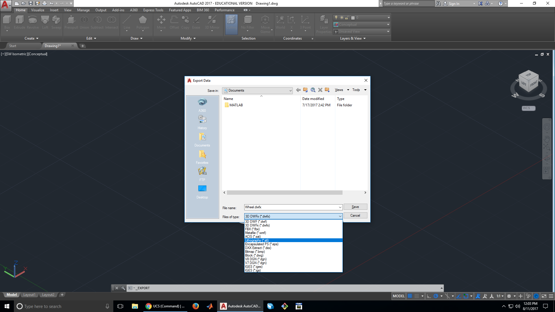
23. Save the wheel and export as a .stl file
At this point, the wheel is done. All that’s left to do is to export it as an stl file so that it can be 3D printed.

 x`
x`