ece3400-2018
This project is maintained by CEI-lab
Lab 1: Microcontroller
ECE 3400 Fall 2018
Objective
In this introductory lab, you will learn how to use the various functionalities of the Arduino Uno and the Arduino IDE, as well as the GitHub repository. Your team will brainstorm and construct a simple functional Arduino program using multiple external components and the Arduino Uno. Once you have this basic understanding, you should put together your robot and have it perform a simple autonomous task. If you are already familiar with the Arduino, feel free to let those less familiar focus on the lab, and engage in some of the other tasks mentioned at the end of this page.
Pre-lab Assignment
By the beginning of your lab session, your team must have created a GitHub account. We will use GitHub to share and save code (source control), and to manage your team website. To create a GitHub account go to github.com and request a private account via the educational discount (https://education.github.com/discount_requests/new). This link has helpful remarks on how to use GitHub, and how to build a website.
In addition, you should have reviewed the Arduino Reference (http://arduino.cc/en/Reference/HomePage) page and made yourself familiar with its layout and some basic functions and syntax. Also, read up on how the Parallax Continuous Rotation Servo is used in a circuit: http://www.parallax.com/downloads/continuous-rotation-servo-documentation.
Documentation
Throughout this lab and ALL labs, remember to document your progress on your website. Add anything that you think might be useful to the next person doing the lab. This may include helpful notes, code, schematics, diagrams, videos, and documentation of results and challenges of this lab. You will be graded on the thoroughness and readability of these websites.
Remember, all labs are mandatory; attendance will be taken at every lab. All labs will require you to split into two sub-teams, be sure to note on the website what work is carried out by whom. Please make new teams for every lab!
Procedure
Grab the box that has your team number written on it.
Split into two teams. Each team needs:
- 1 Arduino Uno (in the box)
- 1 USB A/B cable (in the box)
- 1 Continuous rotation servos
- 1 Pushbutton
- 1 LED (any color except IR!)
- 1 Potentiometer
- Several resistors (kΩ range)
- 1 Solderless breadboard
Communicating between the Uno and IDE
Open up the Arduino IDE and open the “Blink” example code, or “sketch.” Do this by clicking File > Examples > 1.Basics > Blink. The code should pop up in a new window. To program your Arduino, click the checkmark to compile your code and then the right-pointing arrow to upload (program) it. Note: When you click the right arrow, your code will automatically be re-compiled, so clicking the checkmark isn’t strictly necessary. The Uno’s on-board LED should blink on and off every second. If the LED does not blink, check that the UNO is connected to the correct COM port by looking at the Tools > Serial Port list.
Once your Uno is working as it should, take a minute to look over the code and understand what it is doing. Arduino code is similar to C and is relatively easy to understand just by looking at it. One of the first things you’ll notice are two functions – setup and loop. All Arduino sketches (programs) require these two functions or they will not compile. The setup function runs only once at the beginning of the program. The loop function executes after the setup function and runs continuously until the Uno is turned off.
Refer to the Arduino Reference (http://arduino.cc/en/Reference/HomePage) to understand what the other functions in the Blink sketch do. If you have any questions, ask!
Modify the Blink Sketch
Now that you understand the basics of Arduino code, modify the existing code to work for an external LED (instead of the one on-board that is hard-wired to pin 13). Be sure to connect the LED to a digital pin. Repeat this for each of the digital pins to make sure that all digital pins work. Pins can stop working if you source too much current from them - ALWAYS add a series resistor of at least 300 ohm.
The Serial Monitor and the Analog Pins
The Uno has several analog pins that work as an input only (these don’t need to be explicitly configured as input pins). Use a potentiometer to input different analog voltages and print these values out to the screen.
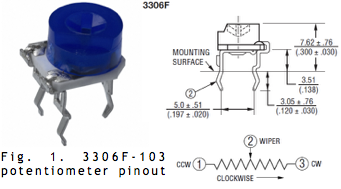
Figure 1 shows a pinout diagram for the potentiometer. You can also access the datasheet for the potentiometer here - it is part number 3306F-103. The Uno pins read voltage, not resistance, so set up a simple voltage-divider circuit using the potentiometer and a resistor. Connect the output of the circuit to the analog pin, and be sure to connect the ends of the circuit to the ground and Vcc pins on the Uno. As previously mentioned, it is wise to put a ~300 ohm resistor in series with anything you connect to a pin, whether it be an input or an output. This way, if you have set something up incorrectly, it is less likely that you will burn out the pin or any connected components.
Using the Arduino Reference webpage as a guide, think about how to write your setup and loop functions so that the serial monitor outputs the circuit’s analog value every half-second. When defining the analog pin number, use the code int PINNAME = AX;, where PINNAME is your variable name and X is the analog pin number. You can view the serial monitor by clicking on the magnifying glass in the top right corner of the IDE. Of course, the USB A/B cable must be connected to both the Uno and the computer for the serial monitor to work. Repeat the above with all analog pins to make sure that all analog pins work.
While there are examples in the IDE that have code for the serial monitor and analog pins, try to figure out how to write the code on your own using just the Arduino Reference page for help. If you get stuck, feel free to collaborate with a neighboring group or ask a TA for assistance.
Analog Output
The Arduino can only output digital signals. In order to create an ‘analog output’, you can use a pulse-width modulator (PWM) – essentially a very fast square wave with differing on and off times. Depending on the load this square wave is often averaged out, creating the effect of an analog or fractional output voltage.
To see how this works, use your existing code for the potentiometer reader to change the brightness of an external LED. Connect an LED to a digital pin (in series with a resistor!) and set it up as an output pin. The digital pin must have PWM capability; this is available for pins with a tilde (~) symbol next to them. Then use the analogWrite function to map the potentiometer value to a brightness value.
Parallax Servos
Your robot propulsion will be based on Parallax Continuous Rotation Servos. You can drive these using the standard Arduino Servo.h library. Connect one servo to the Uno by hooking up the white wire to a digital pin (set to output) with PWM capability. The red wire goes to the 5V output pin, and the black wire goes to ground. Note: Because servos use a lot of power and can be noisy, you’ll eventually connect the red and black wires to an external power supply consisting of rechargeable 5V battery pack.
To use the Servo library, insert the line #include
The servos you have are different than standard servos – most servos can only rotate a certain amount, while the Parallax ones you have rotate continuously. Because of this difference, it is important to note that calling the Servo function ServoName.write(X);, where X is an integer from 0 to 180 and ServoName is the servo variable’s name, corresponds to a speed rather than a position. If X is 90, the servo will stop. If it is 0, it will rotate one way at full speed, and if it is 180 it will rotate the other way at full speed. Experiment with values of X until you understand how the servo operates. Then implement this into your previous code to change the speed of the servo dependent on your potentiometer.
Assemble and Run Your Robot
Whoever finishes first should start assembling the robot. For this you will need a chassis, screws, a 9V battery with clip, and ball bearings. Examine all of your parts, and make sure you understand the purpose of each - make the TAs aware immediately if anything is missing. Once the robot is assembled complete with two servos and a ball bearing, hook it up to an Arduino and make it perform a short autonomous task. E.g. make it drive in figure eights, or a square or similar; remember to record videos for the website.
If you have plenty of spare time, feel free to add line sensors. Try making the robot follow a black line on the floor and make it go as fast as possible; this will help you in the final challenge.
If you finish early
Already a whiz at Arduino? No worries, there are plenty of other things to do. If you want credit for this extra work, be sure to add your documentation to the website.
Soldering
If you run out of things to do, feel free to practice soldering of components and wires. Check out these helpful videos on soldering, and desoldering. You can find old soldering wires and electronic components in the large bin in the lab. It is a really good idea to practice ahead of time to learn the technique to avoid, for example, damaging your actual components, or breaking wires during the competition. Be sure to always obey the following rules:
- Wear goggles when soldering
- Tie your hair if it can get in the way of your work
- Wash your hands after soldering
- Clean the solder iron tip often, and when finished (tin it before storing the iron)
- Turn off the soldering station when you are finished
- Clean your work area!
Mechanical Parts
All the mechanical parts for the robot can be found on this site (ADD SITE!!!). Feel free to start making new parts in Solidworks or Autocad (installed on all lab machines), if you wish. This page has basic info on how to design new parts - reach out to one of the TA’s to show you how to fabricate it.
Sensors
Start thinking about what sensors you want on your robot. How many are needed? Check out the lab stock. Remember, the entire robot must cost less than <$100. If you would like to purchase sensors/actuators that are not in the lab, write up an email to the TA’s and the instructor explaining where to buy it and the reason for buying. We will consider these purchases on a case by case basis. Shipping and tax will be taken out of your budget. The earlier you decide on these the better - shipping to Ithaca can easily take a week.
Wrap-Up
Keep your Arduino Unos and Parallax servos in the box dedicated for your team. All other components can be placed back into their appropriate bins. There should also be two battery banks in your box, it would be a good idea to mark them with your team number. We will be using these to power the robot this year (one spare, one onboard) - no non-rechargeable batteries will be accepted. Think green! It is your responsibility to keep the batteries charged.
If you decide to use any private parts for your robot, be sure to clearly label them as such. Throughout the semester we will spot check boxes, to ensure that no team has taken more than their share of parts. If your own components are not labeled as such, they will be removed.
Use GitHub on the computer to upload and save your code, be sure to add appropriate commits. The lab computers will NOT keep any data locally (i.e., on them). Once you log off, the data will eventually be lost (typically overnight). Save your data on a flash drive or other means before you leave the lab.
Grading
Check the grading rubrics here.
You need to document this lab thoroughly on your website, feel free to add ideas/comments this lab inspires regarding your future robot; the TA’s will check the website by the deadline noted here. Since both sub-teams will be completing the same task during the lab, you are welcome to only document one of these on the website.
Note that to encourage concise and engaging websites, we have a cap on the number of words allowed to discuss the lab: 2,000 (not including code snippets) - Feel free to write much less! You can easily make up for the lack of words by adding figures, photos, and videos with captions!
Remember to have a TA note your attendance before heading out.