ECE4960-2022
Course on "Fast Robots", offered Spring 2022 in the ECE dept at Cornell University
This project is maintained by CEI-lab
Cornell University: ECE 4960/5960
Lab 3 Sensors
Objective
The purpose of this lab is to equip the robot with sensors - the faster the robot can sample and the more it can trust a sensor reading, the faster it is able to drive. Note that this lab has two components related to the Time-of-Flight Sensors (ToF) and the Inertial Measurement Unit (IMU) - each component has a prelab. Be sure to start in good time. This lab will take considerably longer than Lab 1 and 2!
Parts Required
- 1 x SparkFun RedBoard Artemis Nano
- 1 x USB cable
- 2 x 4m ToF sensor
- 1 x 9DOF IMU sensor
- 1 x Qwiic connector
- 1 x Ruler or graph paper
Prelab
In the first half of the lab, we will setup the Time-of-Flight (ToF) sensor, which is based on the VL53L1X. Please skim the manual, and check out the datasheet before beginning this lab. Note the sensor I2C address.
The address of the sensor is hardwired on the board which means you cannot (as is) address the two sensors individually. You can change the address programmatically (while powered) or you can enable the two sensors separately through their shutdown pins. Decide and argue for which approach you want to use. Given their range and angular sensitivity, think about where you will place them on your robot to best detect obstacles in future labs. Discuss scenarios where your robot will miss obstacles.
The purpose of the second half of the lab is to setup your IMU, which will enable your robot to estimate its orientation and angular rate of change. Note that there are several ways to compute the orientation, through lectures and this lab you should understand the trade-offs of each approach.
To help you get through the lab, consider installing SerialPlot to help visualize your data.
Also, read up on the IMU. While Sparkfun has a different breakout board, their information gives a nice quick overview of the functionality, and their software library works well. The ICM-20948 datasheet can be found here.

Think ahead!
While you can choose to ignore the robot in this lab, it is worth hooking up all connectors and routing the wires with their position in the robot in mind, such that you won’t have to redo too much later on. Discuss your thinking in the write-up. Sketch out a diagram of all the wires you will need to connect:
- Think about which connections you want to be detachable and which can be permanent
- Think about which side of the sensors you mount the wires from.
- Think about the placement of each sensor in the chassis and how long the wires have to be.
Lab 3(a): Time of Flight Sensors
Lab Procedure
- Using the Arduino library manager, install the SparkFun VL53L1X 4m laser distance sensor library.
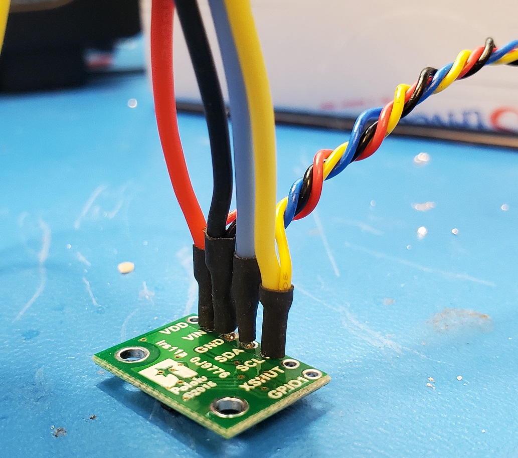
- Connect the VL53L1X breakout board to the Artemis board using the QWIIC-to-cable connector. Here’s an example of wiring which allows daisy chaining of two sensors.
-
Scan the I2C channel to find the sensor: Go to File->Examples->Wire and open Example1_wire. Browse through the code to see how to use i2c commands. Run the code. Does the address match what you expected? If not, explain why.
-
The ToF sensor has three modes, that optimize the ranging performance given the maximum expected range. Discuss the pros/cons of each mode, and think about which one could work on the final robot.
<pre>
.setDistanceModeShort();  //1.3m
.setDistanceModeMedium(); //3m
.setDistanceModeLong();   //4m, Default
</pre> -
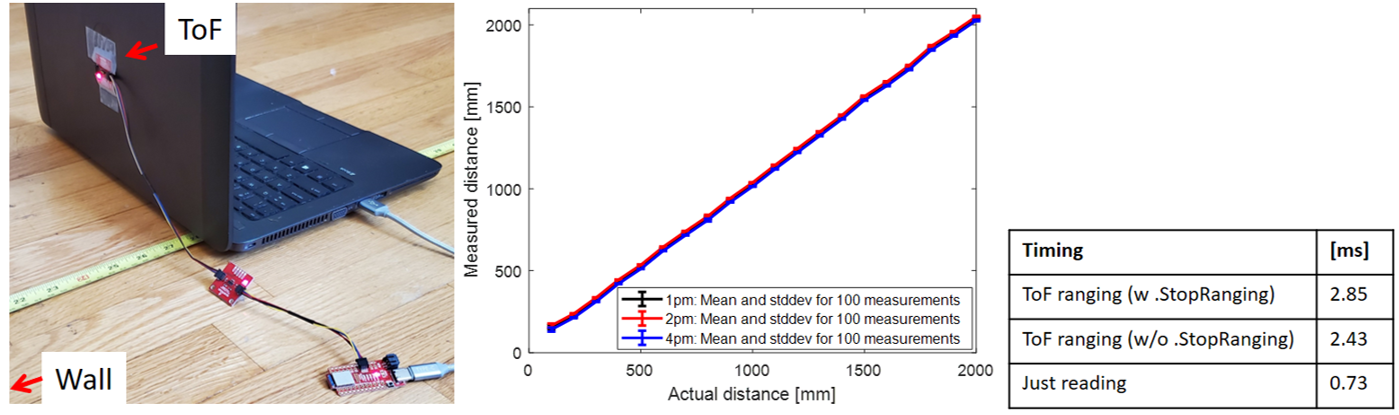
Test your chosen mode using the “..\Arduino\libraries\SparkFun_VL53L1X_4m_Laser_Distance_Sensor\examples\Example1_ReadDistance” example and a ruler. Document your ToF sensor range, accuracy, repeatability, and ranging time. Check and discuss whether the sensor is sensitive to different colors and textures.
- Using notes from the pre-lab, hook up both ToF sensors simultaneously and demonstrate that both works.
- Fyi, don’t use the Example1_wire code to do this, it works poorly when multiple sensors are attached.
Additional tasks for ECE5960 students:
-
Many distance sensors are based on infrared trasmission. Discuss a couple, highlight the differences in their fuctionality and the pros/cons of each.
-
The ToF sensor has a timing budget that affects sensor accuracy, range, measurement frequency, and power consumption. For more detail please check Section 2.5.2 in the manual. Below are some relevant functions. Try out some settings, and discuss your choice of settings related to the anticipated speed of your robot.
<pre>
.setIntermeasurementPeriod();
.setTimingBudgetInMs();
</pre> -
Not all ToF measurements will be accurate, especially when the robot is moving fast. To deal with this, the ToF sensor has two parameters, “signal and sigma”, that tell you whether the measurement you read is valid. These features are detailed in Sec. 2.5.4 in the manual. To see how often failure modes occur, run the “..\Arduino\libraries\SparkFun_VL53L1X_4m_Laser_Distance_Sensor\examples\Example3_StatusAndRate” example. Try rapidly changing the distance from the sensor to an object and describe what happens. Consider how this will impact your motion implementation in future labs.
Lab 3(b): IMU
Lab Procedure
Setup the IMU
- Using the Arduino library manager, install the SparkFun 9DOF IMU Breakout - ICM 20948 - Arduino Library.
- Connect the IMU to the Artemis board using I2C wiring.
- Run the “..\Arduino\libraries\SparkFun_ICM-20948\SparkFun_ICM-20948_ArduinoLibrary-master\examples\Arduino\Example1_Basics”.
- Note the AD0_VAL definition. What does it represent, and should it be 0 or 1?
- Check out the change in sensor values as you rotate, flip, and accelerate the board. Explain what you see in both acceleration and gyroscope data.
Accelerometer
- Use the equations from class to convert accelerometer data into pitch and roll. To use atan2 and M_PI, you have to include the math.h library.
- Show the output at {-90, 0, 90} degrees pitch and roll. Hint: You can use the surface and edges of your table as guides to ensure 90 degree tilt/roll.
- How accurate is your accelerometer? You may want to do a two-point calibration (i.e. measure the output at either end of the range, and calculate the conversion factor such that the final output matches the expected output).
- Try tapping the sensor and plot the frequency response.
- What frequency spectrum does the “unwanted noise” have? Here’s a helpful tutorial to do a Fourier Transform in Python
- Use these measurements to guide your choice of a complimentary low pass filter cut off frequency (recall implementation details from the lecture. Discuss how the choice of cut off frequency affects the output.
Gyroscope
- Use the equations from class to compute pitch, roll, and yaw angles from the gyroscope.
- Compare your output to the pitch and roll values from the accelerometer and the filtered response. Describe how they differ.
- Try adjusting the sampling frequency to see how it changes the accuracy of your estimated angles.
- Use a complimentary filter to compute an estimate of pitch and roll which is both accurate and stable. Demonstrate its working range and accuracy, and that it is not susceptible to drift or quick vibrations.
Additional tasks for ECE5960 students
- Use the equations from class to convert magnetometer data into a yaw angle.
<pre>
      xm = myICM.magX()*cos(pitch) - myICM.magY()*sin(roll)*sin(pitch) + myICM.magZ()*cos(roll)*sin(pitch); //these were saying theta=pitch and roll=phi
      ym = myICM.magY()*cos(roll) + myICM.magZ()*sin(roll_rad);
      yaw = atan2(ym, xm);
</pre>
- While keeping the IMU horizontal, change its orientation and find the magnetic north (feel free to ignore magnetic declination)
- Check that the output is robust to small changes in pitch
Write-up
To demonstrate that you’ve successfully completed the lab, please upload a brief lab report (<1.000 words), with code snippets (not included in the word count), photos, and/or videos documenting that everything worked and what you did to make it happen.